Draft
Mounting the car unit # #
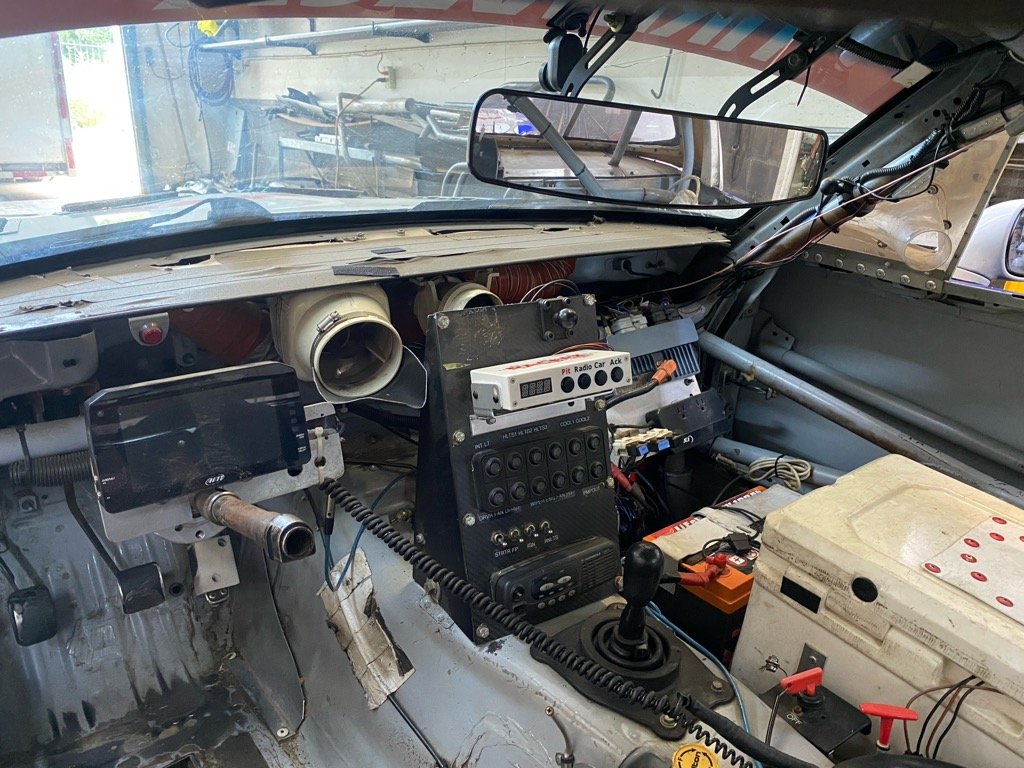
Use the supplied mount to mount the unit in a convenient location within reach of the driver. Also mount it in a location to keep it out of any moisture that might enter the car.
Wiring the car unit #
Below is a picture of the connectors on the back of the car unit.
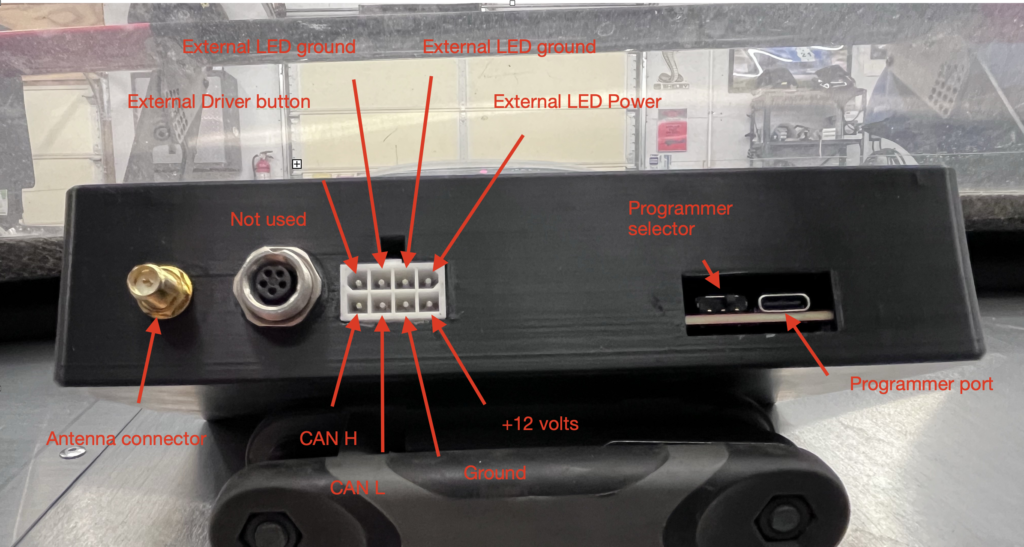
8 pin connector #
- +12 volts: connect through a 5 amp fuse to the car’s 12 volt source.
- Grounds: connect to chassis ground.
- CANL and CANH: connect with a twist wire pair to the car’s CAN network
- External LED: can be connected to a external LED. Is triggered with the “pit now” command from Crew Chief
- External button: can be used for a steering button
5 pin AIM connector # #
To be removed
Programing #
- Programmer port: USB-C connector for loading firmware updates
- Programmer selector: To select whether the CPU or radio is programmed
- Normal operations: As seen in the picture above the selector needs to towards the right.
- Radio pairing: The selector needs to be to the left.
Antenna connections #
These are connections for the connecting the car antenna. Use the supplied coax cable.